
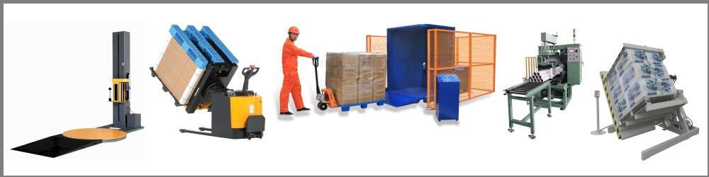
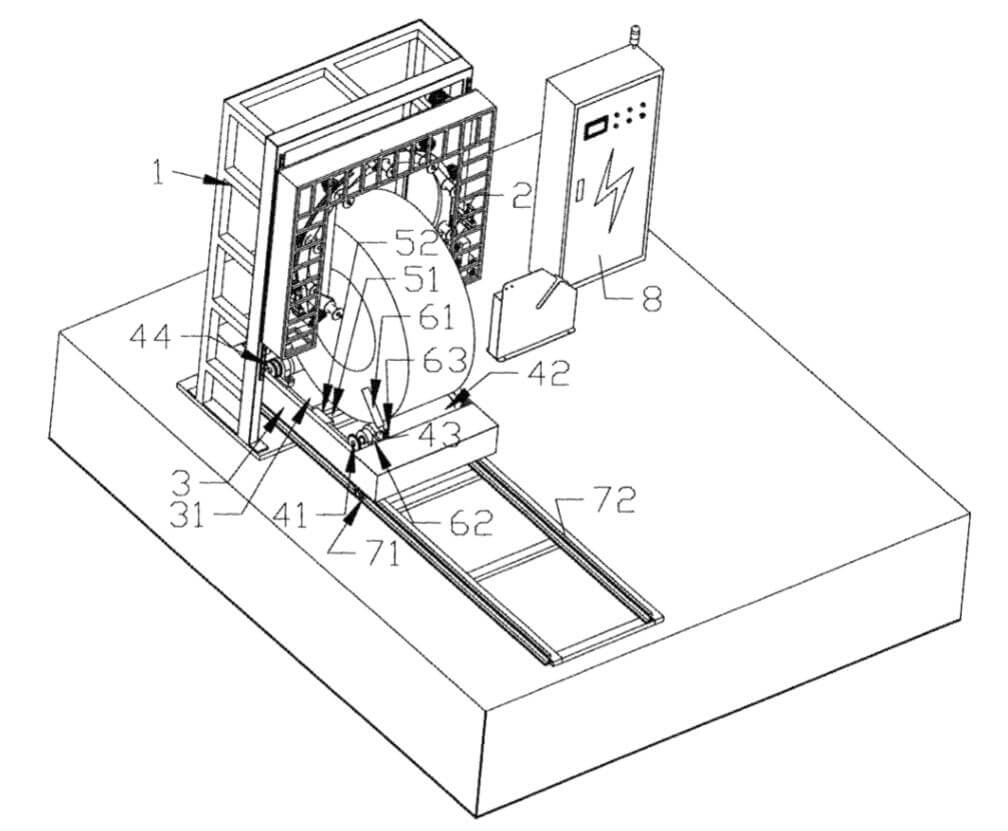
1. Large-scale automatic orbital coil wrapping machine, including frame, rotary winding device, rotary power mechanism, bearing table, conveying device, rotary guide device, ejector device, control device, rotary winding device is installed on the frame, and the bottom of the frame Equipped with a conveying device perpendicular to the frame, the conveying device is arranged perpendicular to the frame, a bearing table is installed on the conveying device, a rotary power mechanism is installed on the bearing table, and a set of rotation is set on the upper part of the rotary power mechanism and below the frame. The guide device is provided with an ejection device in the middle of the rotating power device. The rotating power device includes two rotating main shafts, two rotating rollers, a driving gear, a driven gear, a chain, a rotating power device, and a rotating main shaft mounting bearing. There is a concave bearing groove in the middle of the bearing table, and two rotating spindles are arranged transversely in the bearing groove. On a rotating main shaft, a driving gear and a driven gear are connected together by a chain, and the driving gear is also connected with a rotating power device.
2 The large-scale automatic orbital coil wrapping machine, wherein the ejection device includes an ejection roller, two ejection swing arms, an ejection power device, and the ejection stick is provided in the rotation power device In between, the two ends of the ejector stick are respectively provided with an ejector swing arm, and the other end of the ejector swing arm is connected with an ejector power device. The ejector power device is a swing cylinder. The output end of the swing cylinder is connected to the ejector through a cam structure. Swing arm connection.
3.The large-scale automatic orbital coil wrapping machine, wherein the rotary guide device includes two groups of guide rods, a guide rod fixing seat, and a pair of connecting ears, and each group of guide rods are respectively arranged in a carrying groove. On the side, the guide rod is connected to the guide rod fixing seat through the connecting ears, and the guide rod fixing seat is fixedly installed in the bearing groove.